flyweight
Spice up your life with FM and Feedback
Heeft iemand hier zijn Behringer Model D heeft gemod voor beter OSC stabiliteit?
Als ik het goed begrijp is de Model D gebaseerd op de oude moog dus is er een kans dat dit hieronder kan werken.
Meer stabiele OSC's heeft iig mijn voorkeur.
source: Synth DIY
Als ik het goed begrijp is de Model D gebaseerd op de oude moog dus is er een kans dat dit hieronder kan werken.
Meer stabiele OSC's heeft iig mijn voorkeur.
source: Synth DIY
Curiously enough, although the electronic circuits integrates tempco (temperature compensation) resistors, the pitch stability of old oscillator boards is far from ideal. When analyzing the component layout it is clear that problem come from the fact the tempco resistors are located too far away from the two transistor arrays involved in the V/OCT conversion. To ensure a good temperature compensation the tempco resistors (R20 OSC1, R71 OSC2 and R119 OSC3) ought to be closely associated with the transistor arrays. The modification consists in desoldering the tempco resistors, solder leads to them and gluing them to the transistor arrays (IC2 OSC1 & OSC2; IC7 OSC3).
To correct this, we can move the tempco resistors (R19,R71,R119) as close as possible to the corresponding transistor arrays (IC2 et IC7) in order to obtain a quick and efficient feedback between these components.
- Unsolder R20 from the printed circuit board, then solder a pair of wires to the legs of R20 on one side and to the corresponding holes on the PCB on the other side. Then R20 is inserted inside the IC socket of IC2 under IC2 (no need to glue R20, it will stay in place).
- Unsolder R71 from the printed circuit board, then solder a pair of wires to the legs of R71 on one side and to the corresponding holes on the PCB on the other side. Then R71 is placed on top of IC2 and tied to it with thin wires (sewing wire or nylon wire).
- Unsolder R119 from the printed circuit board, then solder a pair of wires to the legs of R119 on one side and to the corresponding holes on the PCB on the other side. Then R119 is inserted inside the IC socket of IC7 under IC7 (no need to glue R119, it will stay in place).
One may also use thermal grease to ease thermal exchanges between components but this is not compulsory to do so.
This modification is really worth being made because it dramatically reduces the warming delay before playing in tune : less than 5 minutes is required after the modification while 20 minutes at least were required before. Furthermore, the tuning between oscillators becomes nearly immediate.
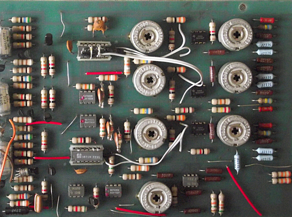
BEFORE MODIFICATION
Location of the tempco resistors (big black resistors)
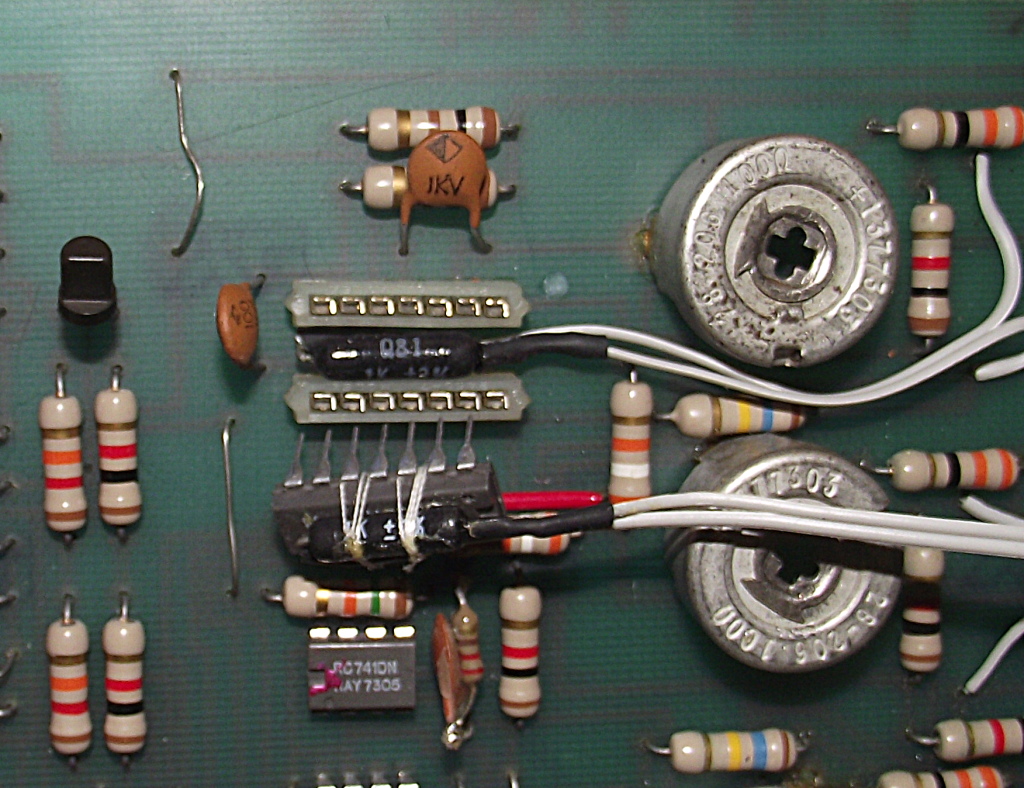
Connexion des résistances tempco sur et sous les réseaux de transistor
Detail of the fixation of R19 & R70 beneath and onto IC2

")