Ik zit er aan te denken om bij mijn Tr-909 de tune depth mod te doen, welke op http://www.colinfraser.com/tr909/909mods/909mods.htm staat..
Ik heb mezelf aangeleerd om het een en ander met een soldeerbout te kunnen doen, door middel van wat experimentjes en onder andere een bouwkitje, dus een beetje solderen kan ik wel..
Probleem is alleen dat ik verder niet echt kennis bezit qua electronica..
Nu zijn op zich alle mods die daar staan me duidelijk, omdat ze gewoon goed uitgelegd staan, alleen begrijp ik nu net die mod die ik wil niet helemaal..
dit is het totale verhaaltje;
Ik snap het helemaal tot aan het laatste stukje over de potential divider.
Als ik R28 vervang door een potmeter met dezelfde waarde, dan hoef ik me neem ik aan niets van die potential divider van 10k aan te trekken..?
Verder begrijp ik het laatste stukje niet geheel..
Zou iemand me hier iets meer duidelijkheid over kunnen verschaffen..?
Ik heb mezelf aangeleerd om het een en ander met een soldeerbout te kunnen doen, door middel van wat experimentjes en onder andere een bouwkitje, dus een beetje solderen kan ik wel..
Probleem is alleen dat ik verder niet echt kennis bezit qua electronica..
Nu zijn op zich alle mods die daar staan me duidelijk, omdat ze gewoon goed uitgelegd staan, alleen begrijp ik nu net die mod die ik wil niet helemaal..
dit is het totale verhaaltje;
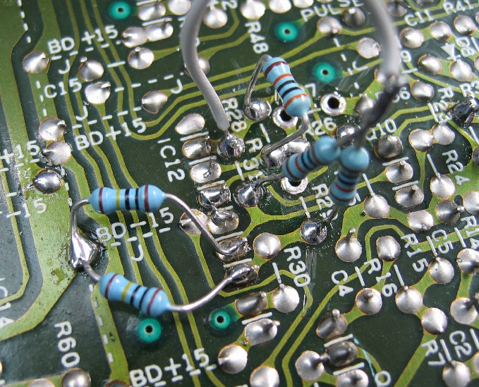
If you refer back to the schematic, you'll see the Tune envelope (ENV 3) generated on C9 passes through IC12A before it reaches what is essentially a control voltage input for the oscillator at the junction of R29 and R31.
This voltage can't fall to 0v, or the oscillator would cut-out altogether. So R27, the 1.5M resistor at the negative input of IC12A, adds a fixed voltage offset to the output of IC12A which sets the minimum frequency of the oscillator. This means we can't vary the tune depth just by putting a potential divider between the output of IC12A and the oscillator control input, or by making the gain of IC12A variable.
To get round this, I removed R27, and restored the effect of the offset voltage at the CV input with a pair of 1Meg resistors to both the positive and negative inputs of IC12B - at the other ends of R29 and R31. These 1M resistors come from the -15v supply.
This alters the circuit so that IC12A is providing an envelope voltage that now falls all the way to 0v. So we can change the amount of pitch sweep with a potential divider, or by making the gain of IC12A variable (replace R28 with a pot). I used a 10k pot as a potential divider, as I didn't have a suitable pot to replace R28 (the gain setting resistor of IC12A).
To break the link between the output of IC12A and the oscillator control input, I removed the two resistors R29 and R31, and replaced them with new resistors of the same value soldered to the pads by one lead each, and then connected together by their other.
Ik snap het helemaal tot aan het laatste stukje over de potential divider.
Als ik R28 vervang door een potmeter met dezelfde waarde, dan hoef ik me neem ik aan niets van die potential divider van 10k aan te trekken..?
Verder begrijp ik het laatste stukje niet geheel..
Zou iemand me hier iets meer duidelijkheid over kunnen verschaffen..?


 Ik was nooit echt tevreden met de attack in de kicks van mijn 909, die miste net wat power vond ik altijd, wat nu door deze mod dus verholpen is
")