een mooie module voor de liefhebbers van Arduino:
een perfect afgebouwde nw2s::b
alle info op nw2s.net
deze module is te koop voor 400€
hier alvast een voorsmaakje:
een perfect afgebouwde nw2s::b
alle info op nw2s.net
deze module is te koop voor 400€
hier alvast een voorsmaakje:
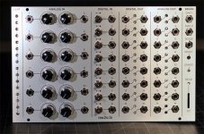
PRODUCT DESCRIPTION:
Beat Clock
Displays the first clock’s state. It shows four groups of four beats, but will support any number of major and minor divisions.
CV Input Jacks
These fully buffered inputs accept -5 to +5V signals at full scale. They can accept further ranges when attenuated by the potentiometer
Input Potentiometers
When there is no jack inserted, these act as 0-5V faders on the 12 inputs. When a jack is plugged in, then it switches to an attenuator for the input signal.
Digital Input Jacks
Accepts either gate or trigger signals from external sources connected to the ON position of the digital input switch. Interrupts are available on each of the inputs.
Digital Input Switches
These ON-OFF-MOMENTARY switches are used to provide digital inputs to the micro controller. When in the center OFF position, the input is low. When in the ON position, the input will be HIGH if no jack is connected, and it will be the same as the input signal if a jack is plugged in. The momentary position will always be HIGH whether there is a jack or not.
Digital Outputs
These outputs provide 0-5V signals as either gate or triggers, depending on how they are set up in code.
Analog Outputs
These CV outputs operate from -5V to +5V as well and are generally suited for CV and envelope generation. They are DC coupled, latched, 12-bit DACs with a gentle low-pass filter applied to stabilize and smooth out the output signal. The output range can be extended to -8V to +8V with a software mod and can extend to -10V to +10V with an op amp modification.
The LEDs are PWM controlled mirrors of the outputs where the brightness indicates the output level.
DAC Outputs
These are AC coupled, bipolar outputs that use the in-built Arduino Due DACs. Their gain is fully adjustable from 0 to infinity via a 25-turn PCB-mounted trimmer to match your intended use of these outputs. They include a 3dB/octave 10kHz low-pass filter on the output buffer.
Noise Output
This output is a bipolar, AC coupled representation of the on-board noise circuit that is fed into one of the Arduino’s digital pins. It also features adjustable gain to match your intended use for this circuit. From the Arduino’s perspective, a copy of the signal is routed to a GPIO pin where it provides a true source of entropy that otherwise does not exist on these tiny microcontrollers.
Reset
This is a recessed momentary switch that allows you to reboot your ‘b from the front panel.
Linked
This LED indicates that a host is connected to the device over Bluetooth. All of the same functions are available as if the device were connected over USB through a virtual Bluetooth TTY. If you do not have Bluetooth and you want to save $15, please let me know when you order and I’ll refund that amount. USB connectivity is provided behind the panel and can be used as long as you have a small place to pass the USB cable through.
Read
This LED indicates SD card activity (technically reads and writes).
Attachments
Last edited by a moderator:
")
